Honeywell XENON 1902 Scanner User’s Manual
About This Manual
This User’s Guide provides installation and programming instructions for the Xenon™ 1900 and 1902 area-imaging scanners. Product specifications, dimensions, warranty, and customer support information are also included.
Honeywell bar code scanners are factory programmed for the most common terminal and communications settings. If you need to change these settings, programming is accomplished by scanning the bar codes in this guide.
An asterisk (*) next to an option indicates the default setting.
Unpacking Your Device
After you open the shipping carton containing the product, take the following steps:
- Check for damage during shipment. Report damage immediately to the carrier who delivered the carton.
- Make sure the items in the carton match your order.
- Save the shipping container for later storage or shipping.
Connecting the Device
Connecting with USB
A scanner or a cordless base can be connected to the USB port of a com- puter.
- Connect the appropriate interface cable to the device first, then to the computer.
Corded Scanner USB Connection: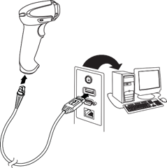
Cordless Base USB Connection: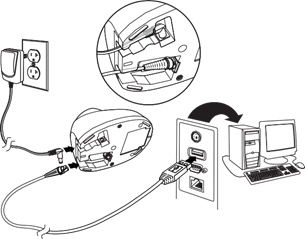
- Make sure the cables are secured in the wireways in the bottom of the cordless base and that the base sits flat on a horizontal surface.
- The scanner beeps.
- Verify the scanner or cordless base operation by scanning a bar code from the Sample Symbols in the back of this manual.
The unit defaults to a USB PC Keyboard. Refer to page 2-4 for other USB terminal settings.
For additional USB programming and technical information, refer to “USB Application Note,” available at www.honeywellaidc.com.
Connecting with Keyboard Wedge
A scanner or cordless base can be connected between the keyboard and PC as a “keyboard wedge,” plugged into the serial port, or connected to a portable data terminal in wand emulation or non decoded output mode. The following is an example of a keyboard wedge connection:
- Turn off power and disconnect the keyboard cable from the back of the terminal/computer.
- Connect the appropriate interface cable to the device and to the terminal/computer
Corded Scanner Keyboard Wedge Connection: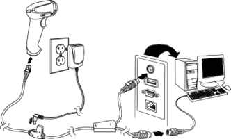
Cordless Base Keyboard Wedge Connection: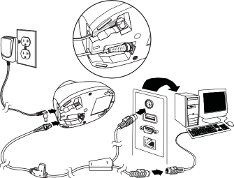
- Make sure the cables are secured in the wireways in the bottom of the cordless base and that the base sits flat on a horizontal surface.
- Turn the terminal/computer power back on. The scanner beeps.
- Verify the scanner or cordless base operation by scanning a bar code from the Sample Symbols in the back of this manual. The scanner beeps once.
The unit defaults to an IBM PC AT and compatibles keyboard wedge inter- face with a USA keyboard. A carriage return (CR) suffix is added to bar code data.
Connecting with RS232 Serial Port
- Turn off power to the terminal/computer.
- Connect the appropriate interface cable to the scanner.
- Corded Scanner RS232 Serial Port Connection:
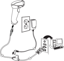
- Cordless Base RS232 Serial Port Connection:

- Corded Scanner RS232 Serial Port Connection:
- Make sure the cables are secured in the wireways in the bottom of the cordless base and that the base sits flat on a horizontal surface.
- Plug the serial connector into the serial port on your computer. Tighten the two screws to secure the connector to the port.
- Once the scanner or cordless base has been fully connected, power up the computer.
This interface programs 115,200 baud, 8 data bits, no parity, and 1 stop bit.
Connecting with RS485
A scanner or cordless base can be connected for an IBM POS terminal interface.
- Connect the appropriate interface cable to the device, then to the com- puter.
- Corded Scanner RS485 Connection:

- Cordless Base RS485 Connection:

- Corded Scanner RS485 Connection:
- Make sure the cables are secured in the wireways in the bottom of the cordless base and that the base sits flat on a horizontal surface.
- Turn the terminal/computer power back on. The scanner beeps.
- Verify the scanner or cordless base operation by scanning a bar code from the Sample Symbols in the back of this manual. The scanner beeps once.
- For further RS485 settings, refer to RS485, page 2-2.
Reading Techniques
The scanner has a view finder that projects a bright red aiming beam that corre- sponds to the scanner’s horizontal field of view. The aiming beam should be centered over the bar code, but it can be positioned in any direction for a good read.

The aiming beam is smaller when the scanner is closer to the code and larger when it is farther from the code. Symbologies with smaller bars or elements (mil size) should be read closer to the unit. Symbologies with larger bars or ele- ments (mil size) should be read farther from the unit. To read single or multiple symbols (on a page or on an object), hold the scanner at an appropriate dis- tance from the target, pull the trigger, and center the aiming beam on the sym- bol. If the code being scanned is highly reflective (e.g., laminated), it may be necessary to tilt the code up 15° to 18° to prevent unwanted reflection.
Menu Bar Code Security Settings
Honeywell scanners are programmed by scanning menu bar codes or by send- ing serial commands to the scanner. If you want to restrict the ability to scan menu codes, you can use the Menu Bar Code Security settings. Please contact the nearest technical support office (see Technical Assistance on page 14-1) for further information.
Setting Custom Defaults
You have the ability to create a set of menu commands as your own, custom defaults. To do so, scan the Set Custom Defaults bar code below before each menu command or sequence you want saved. If your command requires scan- ning numeric codes from the back cover, then a Save code, that entire sequence will be saved to your custom defaults. Scan the Set Custom Defaults code again before the next command you want saved to your custom defaults.
When you have entered all the commands you want to save for your custom defaults, scan the Save Custom Defaults bar code.
Note: If using a cordless system, scanning the Save Defaults bar code also causes both the scanner and the base or Access Point to perform a reset and become unlinked. The scanner must be placed in its base to re- establish the link before any setup codes are entered. If using an Access Point, the linking bar code must be scanned. See Cordless System Operation beginning on page 3-1 for additional information.
You may have a series of custom settings and want to correct a single setting. To do so, just scan the new setting to overwrite the old one. For example, if you had previously saved the setting for Beeper Volume at Low to your custom defaults, and decide you want the beeper volume set to High, just scan the Set Custom Defaults bar code, then scan the Beeper Volume High menu code, and then Save Custom Defaults. The rest of the custom defaults will remain, but the beeper volume settiing will be updated.
Resetting the Custom Defaults
If you want the custom default settings restored to your scanner, scan the Acti- vate Custom Defaults bar code below. This is the recommended default bar code for most users. It resets the scanner to the custom default settings. If there are no custom defaults, it will reset the scanner to the factory default set- tings. Any settings that have not been specified through the custom defaults will be defaulted to the factory default settings.
Programming the Interface
Introduction
This chapter describes how to program your system for the desired interface.
Programming the Interface - Plug and Play
Plug and Play bar codes provide instant scanner set up for commonly used interfaces.
Note: After you scan one of the codes, power cycle the host terminal to have the interface in effect.
Keyboard Wedge
If you want your system programmed for an IBM PC AT and compatibles keyboard wedge interface with a USA keyboard, scan the bar code below. Keyboard wedge is the default interface.
Note: The following bar code also programs a carriage return (CR) suffix.
Laptop Direct Connect
For most laptops, scanning the Laptop Direct Connect bar code allows operation of the scanner in parallel with the integral keyboard. The follow- ing Laptop Direct Connect bar code also programs a carriage return (CR) suffix and turns on Emulate External Keyboard (page 2-18)
RS232 Serial Port
The RS232 Interface bar code is used when connecting to the serial port of a PC or terminal. The following RS232 Interface bar code also pro- grams a carriage return (CR) and a line feed (LF) suffix, baud rate, and data format as indicated below. It also changes the trigger mode to manual.

RS485
Scan one of the following “Plug and Play” codes to program the scanner for an IBM POS terminal interface.
Note: After scanning one of these codes, you must power cycle the cash register.

Each bar code above also programs the following suffixes for each symbology:
|
Symbology |
Suffix |
Symbology |
Suffix |
|
|
EAN 8 |
0C |
Code 39 |
00 |
0A 0B |
|
EAN 13 |
16 |
Interleaved 2 of 5 |
00 |
0D 0B |
|
UPC A |
0D |
Code 128 * |
00 |
0A 0B |
|
UPC E |
0A |
Code 128 ** |
00 |
18 0B |
|
|
MaxiCode |
00 |
2F 0B |
|
* Suffixes programmed for Code 128 with IBM 4683 Port 5B, IBM 4683 Port 9B HHBCR-1, and IBM 4683 Port 17 Interfaces
**Suffixes programmed for Code 128 with IBM 4683 Port 9 HHBCR-2 Interface
RS485 Packet Mode
The following selection allows you to break up large bar code data into smaller packets on an IBM POS terminal. To break up large bar codes into small packets, scan the Packet Mode On bar code below. Scan the Packet Mode Off bar code if you want large bar code data to be sent to the host in a single chunk. Default = Packet Mode Off.
See Manual For details..
Cordless System Operation
Note: This chapter applies only to cordless scanning systems. It does not apply to corded scanners.
How the Cordless Charge Base/Access Point Works
A cordless charge base or an Access Point provide the link between the cord- less scanner and the host system. The base/Access Point contains an interface assembly and an RF communication module. The RF communication module performs the data exchange between the cordless scanner and the interface assembly. The control assembly coordinates the central interface activities including: transmitting/receiving commands and data to/from the host system, performing software activities (parameter menuing, visual indicator support, power-on diagnostics), and data translation required for the host system.
The cordless charge base is also a scanner’s battery charger. Refer to Charging Information, page 3-5, for additional information.
Linking the Scanner to a Charge Base
Turn off power before connecting a base, then power up the computer once the base is fully connected. When the base is connected and powered up, put the scanner in the base to establish a link. The green LED on the base flashes to indicate the scanner’s battery is charging.
If the scanner and base have previously been linked, you do not receive any feedback. If this is the first time that the scanner and base are linked, both devices emit a short chirp when their radios link. At this point, that one scanner is linked to one base.

To determine if your cordless system is set up correctly, scan one of the sample bar codes in the back of this manual. If the scanner provides a single good read beep and the green LED lights, the scanner has successfully linked to the base. If you receive an error tone and the red LED lights, the scanner has not linked to the base. Refer to page 13-6 for troubleshooting information.
Linking the Scanner to an Access Point
Turn on the computer (laptop/desktop). Plug the interface cable into the Access Point first and then into the appropriate port on the computer. The Page button lights up when the connection to the host is made.

Scan the linking bar code on the top of the Access Point to establish a connection between the Access Point and the scanner. The scanner emits a short beep and flashes the green LED to confirm a connection with the Access Point. The Access Point’s Page button remains blue.

Communication Between the Cordless System and the Host
The cordless scanner provides immediate feedback in the form of a “good read” indication (a green LED on the scanner and an audible beep) after a bar code is scanned correctly and the base or Access Point has acknowledged receiving the data. This is possible since the cordless system provides two-way commu- nication between the scanner and the base or Access Point.
When data is scanned, the data is sent to the host system via the base or Access Point. The cordless scanner recognizes data acknowledgement (ACK) from the base or Access Point. If it cannot be determined that the data has been properly sent to the base or Access Point, the scanner issues an error indication. You must then check to see if the scanned data was received by the host system.

RF (Radio Frequency) Module Operation
The cordless system uses a two-way Bluetooth® radio to transmit and receive data between the scanner and the base or Access Point. Designed for point-to- point and multipoint-to-single point applications, the radio operates using a license free ISM band, which sends relatively small data packets at a fast data rate over a radio signal with randomly changing frequencies, makes the cord- less system highly responsive to a wide variety of data collection applications and resistant to noisy RF environments. Bluetooth Class 2 power level provides a communication range of 33 feet (10m) between the scanner and base or Access Point, depending on the environment. See Flexible Power Management, page 3-15, for information about controlling this range.
System Conditions
The components of the cordless system interact in specific ways as you associ- ate a scanner to a base or Access Point, as you move a scanner out of range, bring a scanner back in range, or swap scanners between two cordless sys- tems. The following information explains the cordless system operating conditions.
Linking Process
Once a scanner is placed into a cordless charge base, the scanner’s bat- tery charge status is checked, and software automatically detects the scan- ner and links it to the base depending on the selected link mode.
Refer to Linking the Scanner to an Access Point, page 3-2, for information about linking to an Access Point.
Scanner Is Out of Range
The cordless scanner is in communication with its base or Access Point, even when it is not transmitting bar code data. Whenever the scanner can’t communicate with the base or Access Point for a few seconds, it is out of range. If the scanner is out of range and you scan a bar code, the scanner issues an error tone indicating no communication with the base or Access Point. A cordless charge base can also sound an alarm. Refer to Out-of- Range Alarm, page 3-13.
Scanner Is Moved Back Into Range
The scanner relinks if the scanner or the base or Access Point have been reset, or the scanner comes back into range. If the scanner relinks, you will hear a single chirp when the relinking process (uploading of the parameter table) is complete. Refer to Out-of-Range Alarm on page 3-13 for further information.
Out of Range and Back into Range with Batch Mode On
The scanner may store a number of symbols (approximately 500 U.P.C. symbols; others may vary) when it is out of range and then send them to the base or Access Point when back in range (see Batch Mode on page 3- 16).
You will not hear a communication error tone in this mode, but you will hear a short buzz when you pull the trigger if the radio communication is not working. Once the radio connection is made, the scanner produces a series of beeps while the data is being transferred to the base or Access Point.
Page Button
When you press the Page button on the base or Access Point, the scan- ners associated with that base or Access Point will begin beeping (3 short and 1 long beep). If you pull the trigger on a scanner that is beeping in response, or press the Page button on the base or Access Point a second time, all associated scanners will stop beeping. See Paging on page 3-9 for further information about Page Button settings.
About the Battery
There is a danger of explosion if the batteries are incorrectly replaced. Replace the batteries with only the same or equivalent type recom- mended by the manufacturer. Dispose of used batteries according to the recycle program for batteries as directed by the governing agency for the country where the batteries are to be discarded. Power is supplied to the cordless scanner by a rechargeable battery that is inte- grated in the scanner handle. Batteries are shipped approximately 30% to 60% charged. The battery should be charged for a minimum of 4 hours before initial use to ensure optimal performance.
Charging Information
The battery is designed to charge while the scanner is positioned in the cordless base unit. Refer to Base/Access Point LED Sequences and Meaning, page 3-7, for an interpretation of the Charge Status indicators. Refer to Charge Only Mode (page 3-11) if you need to charge a scanner without linking it to the base.
Place the scanner in the base that is connected to an appropriate power supply. Use only a Listed Limited Power Source (LPS) or Class 2 type power supply with output rated 5 to 5.2Vdc, 1A.
Note: If you are powering the base through the interface cable (for example, a USB cable) and not using an external power supply plugged into the aux port, the current available for charging is reduced and charge times are increased.
Battery Recommendations
- The battery is a lithium ion cell and can be used without a full charge, and can also be charged without fully discharging, without impacting the battery life. There is no need to perform any charge/discharge conditioning on this type of battery.
- Keep the base connected to power when the host is not in use.
- Replace a defective battery immediately since it could damage the scanner.
- Although your battery can be recharged many times, it will eventually be depleted. Replace it after the battery is unable to hold an adequate charge.
- If you are not sure if the battery or charger is working properly, send it to Honeywell International Inc. or an authorized service center for inspection. Refer to Customer Support on page 14-1 for additional information.
Caution: Use only Honeywell Li-ion battery packs, part number 100000495, rated 3.7 Vdc, 7.4Whr, in this device. Use of any non-Honeywell battery may result in damage not covered by the warranty.
Safety Precautions for Lithium Batteries
- Do not place batteries in fire or heat the batteries.
- Do not store batteries near fire or other high temperature locations.
- Do not store or carry batteries together with metal objects.
- Do not expose batteries to water or allow the batteries to get wet.
- Do not connect (short) the positive and negative terminals, of the batteries, to each other with any metal object.
- Do not pierce, strike or step on batteries or subject batteries to strong impacts or shocks.
- Do not disassemble or modify batteries.
Beeper and LED Sequences and Meaning
The scanner contains LEDs on the rear of the unit that indicate linking status, decoding state, and battery condition. The base has LEDs on the top of the unit that indicate its power up, communication, and battery charge condition. The red LED = error; green LED = success of any type. The unit’s audible indicators have meaning as well: 1 razz or error tone = error; 2 beeps = menu change; 1 beep = all other successes.
The table below lists the indication and cause of the LED illumination and beeps for the scanner.
Scanner LED Sequences and Meaning
|
LED Indication |
Beeper Indication |
Cause |
|
Normal Operation |
||
|
Red Flash |
None |
Battery low |
|
Green Flash |
1 beep |
Successful communication or linking |
|
Red, blinking |
Razz or error tone |
Failed communication |
|
Menu Operation |
||
|
Green Flash |
2 beeps |
Successful menu change |
|
Red, blinking |
Razz or error tone |
Unsuccessful menu change |
Base/Access Point LED Sequences and Meaning
The base contains a red LED and the Access Point has a blue LED that indicate the status of the unit and verifies its communication with the host system. The base also has a green LED that indicates scanner battery charge condition.
|
Red or Blue LED - Host Communication |
|
|
Communication Condition |
Red or Blue LED |
|
USB suspend |
Off |
|
Power on, system idle |
On continuously |
|
Receiving data |
Short blinks in multiple pulses. Occurs while transferring data to/from the RF module or the Host port. |
|
Green LED - Scanner Battery (base only, does not apply to Access Point) |
|
|
Charge Condition |
Green LED |
|
Battery not detected or charge suspended |
Off |
|
Pre-charge and charging |
Slow flash, 1 second on, 1 second off |
|
Charge complete |
On continuously |
|
Charge Error |
Fast flash, 300 mSec on, 300 mSec off |
Base Power Communication Indicator
To display the power indicator on a base or an Access Point, scan the Base Power Communication Indicator On bar code. To turn off the power indi- cator, scan the Off bar code. Default = On.
Troubleshooting a Xenon Scanner
The scanner automatically performs self-tests whenever you turn it on. If your scanner is not functioning properly, review the following Troubleshoot- ing Guide to try to isolate the problem.
Is the power on? Is the aiming beam on?
If the aiming beam isn’t illuminated, check that:
- The cable is connected properly.
- The host system power is on (if external power isn’t used).
- The trigger works.
Is the scanner having trouble reading your symbols?
If the scanner isn’t reading symbols well, check that the symbols:
- Aren’t smeared, rough, scratched, or exhibiting voids.
- Aren’t coated with frost or water droplets on the surface.
- Are enabled in the scanner or in the decoder to which the scanner connects.
Is the bar code displayed but not entered?
The bar code is displayed on the host device correctly, but you still have to press a key to enter it (the Enter/Return key or the Tab key, for example).
- You need to program a suffix. Programming a suffix enables the scanner to output the bar code data plus the key you need (such as “CR”) to enter the data into your application. Refer to Prefix/Suffix Overview on page 5-1 for further information.
Does the scanner read the bar code incorrectly?
If the scanner reads a bar code, but the data is not displayed correctly on the host screen:
- The scanner may not be programmed for the appropriate terminal interface.
For example, you scan “12345” and the host displays “@es%.”
Reprogram the scanner with the correct Plug and Play bar code. See Programming the Interface beginning on page 2-1.
- The scanner may not be programmed to output your bar code data properly.
For example, you scan “12345” and the host displays “A12345B.”
Reprogram the scanner with the proper symbology selections. See Chapter 7.
The scanner won’t read your bar code at all.
- Scan the sample bar codes in the back of this manual. If the scanner reads the sample bar codes, check that your bar code is readable. Verify that your bar code symbology is enabled (see Chapter 7).
- If the scanner still can’t read the sample bar codes, scan All Symbologies On, page 7-2.
If you aren’t sure what programming options have been set in the scanner, or if you want the factory default settings restored, refer to Resetting the Factory Defaults on page 1-10.
Troubleshooting a Cordless System
Troubleshooting a Base
Note: Visit the Services and Support section of our website to check for the latest software for both the scanner and the base.
If your base is not functioning properly, review the following troubleshooting guidelines to try to isolate the problem.
Is the red LED on?
If the red LED isn’t illuminated, check that:
- The power cable is connected properly and there is power at the power source.
- The host system power is on (if external power isn’t used).
Is the green LED on?
If the green LED isn’t illuminated, check that:
- The scanner is correctly placed in the base.
- There is external power or 12 volt host power.
- Charge mode is turned on. (See "Beeper and LED Sequences and Meaning" on page 3-6)
The battery is not bad or deeply discharged. In some cases, the scanner’s battery may trickle charge to bring it into an acceptable level and then transition to a normal charge cycle.
Troubleshooting a Cordless Scanner
Note: Make sure that your scanner’s battery is charged.
Visit the Services and Support section of our website to check for the latest software for both the scanner and the base or Access Point.
Is the scanner having trouble reading your symbols?
If the scanner isn’t reading symbols well, check that the symbols:
- Aren’t smeared, rough, scratched, or exhibiting voids.
- Aren’t coated with frost or water droplets on the surface.
- Are enabled in the base or Access Point to which the scanner connects.
Is the bar code displayed but not entered into the application?
The bar code is displayed on the host device correctly, but you still have to press a key to enter it (the Enter/Return key or the Tab key, for example).
- You need to program a suffix. Programming a suffix enables the scanner to output the bar code data plus the key you need (such as “CR”) to enter the data into your application. Refer to Prefix/Suffix Overview on page 5-1 for further information.
Does the scanner read the bar code incorrectly?
If the scanner reads a bar code, but the data is not displayed correctly on the host screen:
- The base or Access Point may not be programmed for the appropriate terminal interface. For example, you scan “12345” and the host displays “@es%.”
Reprogram the base/Access Point with the correct Plug and Play bar code. See Programming the Interface beginning on page 2-1.
- The bas or Access Pointe may not be programmed to output your bar code data properly. For example, you scan “12345” and the host displays “A12345B.”
Reprogram the base/Access Point with the proper symbology selections. See Chapter 7.
The scanner won’t read your bar code at all.
- Scan the sample bar codes in the back of this manual. If the scanner reads the sample bar codes, check that your bar code is readable.
Verify that your bar code symbology is enabled (see Chapter 7).
If the scanner still can’t read the sample bar codes, scan All Symbologies on page 7-2.
Readmore and Download Honeywell XENON 1900/1902 Scanner User's Manual
| Title | : Honeywell XENON 1900/1902 Scanner User's Manual |
| Model | : Xenon 1900/1902 |
| Format | |
| Pages | : 312 Pages |
| Language | : English |
| File Size | : 4.3 MB |
