Honeywell CT87N Owners Manual
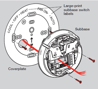
Honeywell CT87N Subbase and base installation
- Pull wires through wire hole. Position coverplate on wall, level and mark hole positions.
- Drill holes (3/16” for drywall, 7/32” for plaster) and tap in supplied wall anchors.
- Pull wire through coverplate and subbase, position over anchors, then insert and tighten mounting screws. Check level if desired.
- Apply the large-print labels to the coverplate, matching the labels on the subbase.
Honeywell CT87N Wiring
- Match each labeled wire with same letter on terminal.
- Use a screwdriver to loosen screw terminals, insert bare wire into slots, then tighten screws.
- Push any excess wire back into the wall opening.

Labels don't match?
If labels do not match letters on thermostat, see table below.
Existing wires Connect to:
R • RH • 4 • V Terminal “R” [1]
Rc Terminal “Rc” [1]
O Terminal “O” [2]
B Terminal “B” [2]
G • F Terminal “G”
W • W1 • H Terminal “W”
Y • Y1 • M Terminal “Y”
C • X • B Do not use [3]
[1] If wires will be connected to both R and Rc terminals, remove metal jumper.
[2] Do not connect both O and B if you have a heat pump. Connect only the O wire. Wrap B wire with electrical tape and do not use.
[3] Do not use C, X or B. Wrap bare end of wire with electrical tape.
[4] If you have two wires, connect wires to R and W.
Honeywell CT87N Fan operation settings

Move the switch to the proper setting for your system:
F: For gas or oil heating systems, leave the fan operation switch in this factory-set position (for systems that control the fan in a call for heat).
E: Change the switch to this setting for heat pump or electric heat systems. (This setting is for systems that allow the thermostat to control the fan in a call for heat, if a fan wire is connected to the G terminal.)
Readmore and Download Honeywell CT87N Manual PDF
| Title | : Download Honeywell CT87N Manual PDF |
| Format | |
| Pages | : 16 Pages |
| Language | : English |
| File Size | : 3 MB |