Honeywell T104F Thermostatic Control PDF
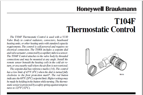
The T104F Thermostatic Control is used with a V110 Valve Body to control radiators, convectors, baseboard heating units, or other heating units with standard capacity requirements. The control is self-powered and requires no electrical connection. The T100A includes a setpoint dial and valve actuator, connected by a capillary tube to a sensor. The T104F Control attaches to the valve body by threaded connections and may be mounted at any angle. Install the remote sensor beneath the heating coils in the cold air return, or on a nearby wall where the air flow is not restricted. The setpoint dial has reference marks (1-6). The control has a low limit of 43°F (6°C) when the dial is turned fully clockwise to the frost protection mark*. The red button indicates the 68°F (20°C) setpoint limit. Higher settings may be made by holding in the button while turning. The thermostatic sensor is protected by a safety spring against temperatures to 125°F (52°C).
Honeywell T104F Thermostatic Specifications

MATERIALS OF CONSTRUCTION:
Body: Industrial grade plastics with low thermal conductivity.
Fastening Ring: Plated brass.
Internal Parts: Brass thermostat capsule, other metals.
TEMPERATURE RANGE: 43° to 79°F (6° to 26 °C).
MAX. SENSOR TEMPERATURE: 125°F (52°C).
MAX. OVERALL DIMENSIONS: 2-1/8 in. (54 mm) wide, 3-5/16 in. (84 mm) long. See Fig. 1.
CAPILLARY LENGTH: 6 ft. 8 in. (2 m).
TEMPERATURE SETTINGS:
These are the setpoint temperatures, which correspond to the setpoint dial reference marks, under ideal conditions. Factors affecting the temperature at the sensor vary for each installation. It may be necessary to adjust the setpoint higher or lower to obtain the desired space temperature.
|
Temperature |
0 |
* |
1 |
2 |
3 |
4 |
5 |
6 |
|
°F |
Off |
43 |
46 |
54 |
61 |
68 |
73 |
79 |
|
°C |
Off |
6 |
8 |
12 |
16 |
20 |
23 |
26 |
Honeywell T104F Thermostatic AVAILABLE VALVE BODIES:
V110 Valve Bodies

OTHER AVAILABLE T100 THERMOSTATIC

CONTROLS (See Fig. 3):
T104A Control with internal sensor.
T104B Control with remote sensor/setpoint.
T104C Control with remote sensor and remote setpoint.
T104V Control with internal sensor and tamper-resistant
setpoint and mounting.
ACCESSORY
A104F1007 Limit Pins.
G111B1053 Bulb guard for protection of sensor when
mounted on the wall.
Honeywell T104F Thermostatic Settings and Calibration
The T104F Control includes an adjustable range limiting pin (order additional pins separately). The pin is factory- set to limit the low range of the control to the frost protection (*) setting (see Fig. 5). The pin can be moved to a different low or high limit setting and lock point, or it can be removed. Use a second pin if both low and high limit settings are desired.
Setting the Limit
To set a limit different from the factory setting, proceed as follows:
- Determine the desired temperature range limit or locking temperature. Select the appropriate number on the adjustment knob to match the desired temperature setting. See Fig. 5.

- Lift the end cap off the adjustment knob. See Fig. 6.

- Remove the adjustment knob from the actuator as follows:
a. Turn the adjustment knob so the desired knob setting is aligned with the white line on the actuator base.
b. Pull the knob off the head or use a screwdriver inserted into one of the slots to pry off the knob. See Fig. 7.
Readmore and Download Honeywell T104F Thermostatic Control PDF Manual
| Title | : Download Honeywell T104F Thermostatic Control PDF |
| Format | |
| Pages | : 8 Pages |
| Language | : English |
| File Size | : 3 MB |